I should explain a few of the design decisions I made with LeoDroid. First, DC Power!
Power Systems
Notice the USB "Power Bank" on LeoDroid's back? That's an 8500mAh NiMH battery capable of delivering 1.5 Amps. They're designed to recharge mobile phones, and come cheap from eBay. You can't build one cheaper, trust me.
If you have built power systems before and didn't know about these brilliant new devices, all you need are these magical words; "5.2V @ 1.5A DC step-up regulator, built-in USB charger, all matched to the battery, less than twenty bucks."
They can be plugged into any standard USB charger. They can charge each other. 5.2V drops to exactly 5V after a Schottky protection diode or LDO regulator. 1.5 amps is enough to spin robot motors.
Unreliable power is one of those things that can ruin your whole day. Buggy self-made power supplies can screw up your whole month. These power banks can be bought for less, in many cases, than the naked battery.
They come in a variety of shapes, colours, sizes, and optional features like solar cells. If one breaks or dies, you just plug in another. You don't have to care about battery chemistry, charge curves, or special connectors. If you use USB-powered Arduinos, there's no soldering required; just unplug from the PC, attach the USB Power Bank, and away you go.
Power Switch
Note well the power switch! The use of a DPDT switch is not accidental - the idea is that when turned on, the battery pack power is connected to the Arduino and Motor Driver - but when turned off, those systems are isolated from each other.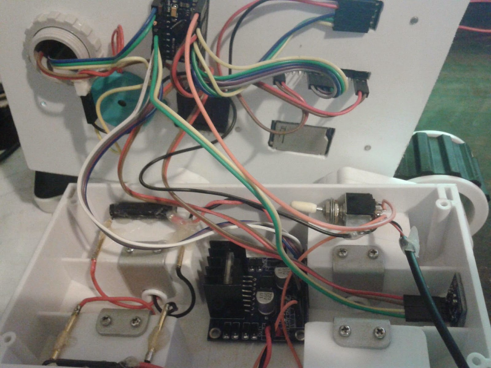 |
| See it? Over to the right, above the wheel well. |
To understand why, notice that the Arduino's USB port isn't connected to the battery, (which would be easy with standard cables) instead we route the power to the RAW pin. This arrangement is absolutely necessary because we can't drive enough power through the Arduino USB port to turn high-current motors. It's not a matter of wire gauge - it's the protection polyfuse. If you try to pull more than 500mA through that fuse, it will shut down.
So we have to run power to the motor driver directly, which means soldering wires. And that same input power has to get to the Arduino, because we're using its on-board regulator to supply the digital circuits with 5V. Power just can't go through the Arduino's USB connector on the way to the motors.
Unfortunately, a problem arises because we occasionally want to plug the Arduino into a desktop PC to upload new program code. We really don't want the battery turned on when doing this, because it's possible that the battery pack (if the PC is underpowered or defective) could feed power INTO the computer and burn out ports, even with the polyfuse. Or the PC could try to charge the battery bank backwards, via the wrong port. Don't cross the streams.
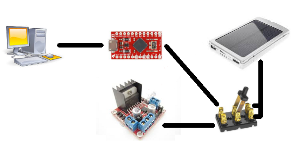
 |
| If you plug your PC into one side and the battery into the other, power can flow ALL the ways. |
If you unplug the battery to prevent this but leave the microcontroller and motors driver connected, the host PC will need to supply all your Droids' needs - including the motors if they happen to suddenly power on because you're debugging, and that will trip the polyfuse.
If you've got good equipment, this will merely reboot the board. If.
With the double-pole switch, "on" means the battery is connected to both controller and motors, and "off" means the controller is safely isolated for programming.
 |
| Throw ze switch, Igor. |
If you use a single-pole switch (or none at all) then you need to be damn sure your equipment (and everything you plug it into) can survive the conditions. Be aware that I have seen USB ports that burst into flame because someone plugged a double-headed cable in twice to the same PC.
Another simple option is to not use the RAW pin but hack up a USB cable so it splits to supply the motor driver as well. Therefore, you'd be forced to unplug the battery USB connector before plugging in the programming USB cable to the PC.
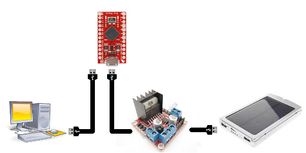 |
| The most foolproof solution, for the usual class of fool. It's still a switch, it's just harder to flip. |
If you think about it, you would be 'manually' performing the action of the DPDT switch by having a mutually exclusive 'power cable' and 'programming cable'. If you intend to do software development, plugging and unplugging over and over can be annoying, and physically break things. Hence the actual switch. Of course, you could leave the switch in the wrong position...
If you don't intend to connect the Arduino to a PC ever again after emplacing it, then a single pole switch is probably fine. But why not do it properly?
(Did I hear someone say "diodes"? Sure, you could use diodes. They'd better be expensive schottky ones, or the voltage drop will take the circuit out of spec. Even good ones are wasting 5% of your power.)
Power Loom
This is such a simple and obvious concept - have a PCB or connector block that is the central power loom. With dupont connectors, I use old 2-row IDC connectors (such as the IDE connectors off dead hard drives) and solder all the pins in each row together to create two 'rails'. Then all the connectors plug into that. It's basically a 10-socket mini power board. |
| Like this, only tiny. |
The alternative, which I see all the time, is the 'daisy chain' that develops when you run power wires to the nearest other powered device.
The 'loom' is not only better electrically (to prevent ground loops) but it makes visually checking hook-up polarity straightforward - if all the black wires are on one side, and all the red on the other, then you're obviously good at the loom end. (This is how we battle Murphy's law.)
It also means you can quickly isolate individual devices without worrying about chained devices. And you can untangle wires easier.
No comments:
Post a Comment