Most of my projects need user interfaces, or at least benefit from one during the development process, so today we have three cheap screens of various sizes and capabilities. As usual, the answers first:
- 1.8TFT SPI - ST7735 1.8" inch SPI TFT LCD Display Module 128x160 - $6
It's small, light, low-requirement and perfectly matches Arduino hardware, especailly the "Micro" gear. This is the one I just bought more of. - HY-TFT240 - ILI9325 2.4" inch TFT LCD Module 240x320 - $12
Twice the screen, twice the cost, twice the pins (at least) needed to drive it and a touch surface as well. A nice screen for larger projects, or where the screen is the project. - CRIUS CO-16 - OLED Display Module V1.0 128x64 - $10
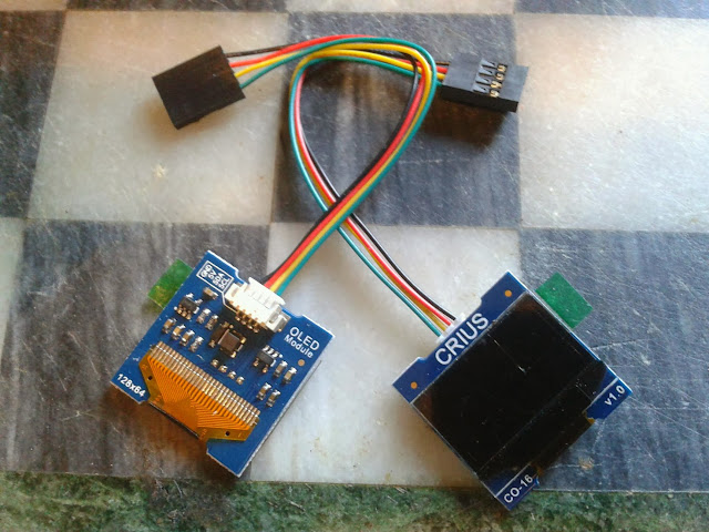
Total fail. It's dead jim. No lights, no response over I2C, both units completely DOA. An ex-parrot. Apparently a "known design flaw". Avoid the V1.0.
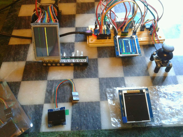
Here's the three screens under test.. going clockwise from the top-left we have the 2.4" inch ILI9325, two ST7735 1.8" inch displays down the right (one powered, one not) and the pair of dead CRIUS OLED displays in the bottom left.

First things first - both functioning screens were bright and clear, and roughly equal in resolution (in terms of absolute pixels per inch) colour range, and backlight brightness. One was just almost twice the size.
But, this clearly doesn't stop you from sending data to the screen, which is the point, after all.

First things first - both functioning screens were bright and clear, and roughly equal in resolution (in terms of absolute pixels per inch) colour range, and backlight brightness. One was just almost twice the size.
I didn't test any of the ancillary functions such as the touchscreen or SD cards. Just the display.
The larger 2.4 inch device has a touchscreen on top and this does affect the visual clarity slightly, so the smaller 1.8 inch display does look sharper when they're side by side - but that advantage will quickly be lost if it's emplaced behind any kind of clear protective panel, whereas the larger one is already ruggedized and covered.
Apart from that, the specifications are very similar. Backlight and 16 bit "RGB565" color. The driver chips have a distinct family similarity, similar start-up and command sets. Colors are vibrant and clear, although blues do need a gamma boost.
I did not do any side-by-side performance testing, because in general that wouldn't be appropriate or very meaningful. There are entirely different software stacks involved. One is SPI and the other Parallel, so the basic hardware protocols have different overheads. From what I could tell from experimentation, the bottleneck in all cases was the Arduino/Atmel. So if I tried, I would really just be measuring how fast the microcontroller's internal ports are.
They even had the same disappointments: both modules are "write only" due to what I would almost consider flaws, but I'll charitably call 'focussed design'. In neither case is it possible to read back values from the display driver chip.
That means you can't read the contents of the framebuffer from either display. That's a real shame, since they have more memory than the Arduino does. And can shift blocks of it around independently. It also means you can't read back configuration registers, or check if the device has crashed, or is actually there at all. You just have to trust that it's listening.
On the 2.4", the octal line drivers (those big old-school chips on the back) that convert 5v logic down to 3.3v are unidirectional... the R/W signal gets through from the microcontroller to the LCD driver, but the lines are one-way. It electronically cannot send a reply back.
The 1.8" SPI device has an even simpler version of the same story; it doesn't break out the SPI MISO line at all, so the apprentice device has no wire to communicate back to the master. (The SD card interface does have both MISO and MOSI lines, but they are 3.3v and will need a voltage converter to play with.)
ST7735 1.8" SPI TFT LCD Display Module 128x160
So, let's start with what I think was the winner. Why? Because (a) it works, (b) it's cheap, and (c) it really only needs five pins to run it. Four, if you connect the reset line to the Arduinos' reset. (Which works fine) Two, if you already use the SPI bus and just need the line selects.
Alright, back up to three if you add in the backlight, which I ran directly to Vcc, but you can connect to an I/O pin and turn on via PWM, if you want variable brightness. So there's flexibility.
Mine was the 'Blue Tab' version, (note the blue tab on the screen 'protector' film, sticking out the bottom left) which turned out to be compatible with the 'Black Tab' variant for the Adafruit GFX libraries I used. I've got to say, I am impressed with Adafruit's software and drivers. They could still be better (but not by much) and they are streets ahead of most of the dross that passes for 'drivers' I've seen.

The single row of pins means it's easy to mount in a breadboard. The mounting holes are nicely placed. I do however feel that the screen itself is not very securely attached to the carrier board, (it feels like two small spots of glue in the bottom corners and the ribbon cable are all that holds it.) and I'm tempted to run a 'weld' of superglue or silicone down the sides of the display where it touches the board, because I'm worried vibration and shock might eventually shake it loose.
That wouldn't be an issue if the screen was 'sandwiched' between the carrier board and a clear panel, say through those bolt holes.
The screenshot is of my new "droid control" software I'll be releasing shortly, which was designed on that very hardware over the last few weeks.
ILI9325 2.4 inch TFT LCD Module 240x320
This was the first one to arrive, and I'm still looking forward to exploring the touchscreen functions. It's a surprisingly large chunk of hardware when you put it next to an Arduino. The thick glass and sensor overlay add to the weight.
Orientation does matter, but really only for one situation. You can't tell in the photo, but the line-graph on the display is scrolling upwards quite smoothly at 50-100FPS. My own drivers get right into the ILI9325, and I make use of the hardware scrolling to achieve this, because otherwise a full screen redraw takes about a second. The hardware scrolling can go up or down, but not sideways. (That I have discovered.. the documentation can be a bit opaque) Which means if you intend to have scrolling text, then it's going to be in 'portrait mode'.

You might think the wider 8-bit parallel data bus would speed things up over the two-wire SPI interface of the smaller device, but you'd be wrong. The Armel has dedicated hardware for the SPI interface, with interrupts and everything, but it's nearly impossible to find an entire microcontroller port where writing one byte will correspond to eight Arduino pins flipping state. And you still have to manage the control pins 'manually'.
Just remember that the larger screen means you have to transfer more data when drawing, and this is already the primary bottleneck. Forget it if you want to do full-screen animation, you'll be lucky to ever break 2fps. (Hardware scrolling uses the trick that only the bottom line changes)
What is this thing? This was actually the prototype for the Sonic Screwdriver Mark I that I built in November. The line graph it's showing is the six-axis output of the accelerometers and gryos on the small device you can see hovering just above the screen. All the lines are flat and boring because I was trying not to bump things while taking the photo.
CRIUS CO-16 OLED Display Module V1.0 128x64
The first thing I've ordered off ebay and hasn't worked at all, although may be the reason you can buy them so "cheaply" given they are more advanced technology (OLED) than the LCD screens above. It was a long shot, I suppose. Perhaps I dreamed too much.

There are a few pages that suggest the OLED module itself is fine, but you have to remove it, hack the board, then solder it back again. Because the tracks that need to be hacked are underneath the ribbon cable connecting the screen to the board. Then you just have to solder a small resistor/capacitor combination across the reset pin and...
Yeah, I don't think so. I have other things to do. The same pages said the reset issue caused 'snow' on boot and I haven't seen a single lit pixel.
They were nicely packed, though, and being individually sealed in anti-static bags I don't expect the seller had the ability or inclination to test them.
I'd be interested to hear from other people about this one. Maybe there is a mode I haven't figured out? Anyone got these to work?